Rack Mount Cable Modem, Part 2 (S34)

My previous cable modem (see previous post) has been in operation for some time now. Apparently SB8200 modems are now approaching the age of incompatibility with Comcast/Xfinity so it is time to upgrade. As a bonus, the S34 also has a 2.5 GbE port for even faster speeds. Yes, I know UniFi has a cable modem available now, and it is cheaper than this. But this doesn’t live in their ecosystem.

Like before, this isn’t a step-by-step guide and assumes some knowledge and tool ownership.

Supplies:

Tools:

How it all comes together:

The first step is to crack the modem open. These are surprisingly easy to get into compared to the SB8200. The two Phillips screws under rubber feet on the bottom need removed, then it’s ready to pry. No label removal this time – don’t be fooled by the depression in the center of the label, it’s not a screw.

Here are the screws:


Let’s take a look at a sides of the partially disassembled case:

You can see one side (the left when looking at it from the front) has nothing more than a seam but the other side (the right when looking at it from the front) has two tabs that need pushed to release. I gently squeezed the sides of the top half of the case until a plastic spudger would slip into the seam and I could gently pry the bottom catches out while pushing in the top tabs.

At this point, the only things holding the PCB into the bottom half of the case are the nut on the coax connector and one screw by the light guide.

This model uses three LEDs through a single guide. This is going to complicate things a bit since they are arranged front-to-back rather than side-by-side and easy to separate like in the SB8200. I suspect we’ll have to handle that with a single custom light guide to route it out to holes in the front panel. My goal is to re-use the SB8200 front panel design since I had them laser cut and have several on hand. Perhaps in a future version I’ll desolder these and move them out to individual indicators on the front panel if they are not bright enough through the 3D printed light guide.


The new case:

These steps are the same as before, so rather than duplicate that writeup, please go read through it.

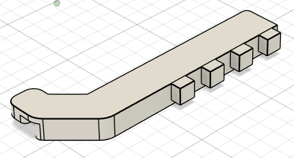
This time, instead of using press-fit PEM standoff inserts, I opted for a 3D printed base plate. The thickness of the base plate plus screw bosses comes in at 9.50mm which is only .50mm less than the 10mm standoffs in the other version. This design uses two of the screw holes in the PCB and re-uses the case screws so no additional hardware is required.  A small shelf supports the other end of the PCB because there are no mounting holes and the bottom heatsink blocks much of the space underneath. This edge is secured with a small strip of double sided mounting tape (3mm by 40mm). I included pockets on the bottom for two 30mm long by 3/4″ wide (mixing units because the tape is sold as 3/4″ wide) pieces of double sided mounting tape to keep it low in the enclosure.

It would likely be fine in PLA but I’m going to use ASA for it’s higher heat tolerance just to be safe.

Here is the final printed version showing the bosses and mounting tape pockets.

And to deal with the LED issue, a custom light guide to be 3D printed in transparent PETG. Future refinement may be necessary but this should move some light from the board to the openings.

These photos show some light guide progression, moving from a design test in white PLA to transparent PETG at default settings then transparent PETG with refined settings. Though not optically clear, it is significantly more transparent. I’ve done enough testing now with the Bambu transparent PETG to know I won’t get much better finishes than this without significant tuning. This is probably worthy of a separate post, but here are the basics. First, I printed in white PLA to get a baseline for the model, test fitment, and refine the design since I have great success with PLA. Next, I printed with freshly opened transparent PETG using the default slicer settings for “0.16mm High Quality” using the default “Bambu PETG Transparent” filament profile to get a baseline for the material. This is shown on the bottom left below. From there, I followed the Bambu Lab guide for transparent PLA/PETG. This version is shown on the top right below. I then adjusted settings a bit more to change the solid infill pattern and ensure the infill direction aligned with the major axis of the part. Shown on the bottom right below and the series of three comparisons below. In those three, the optimized settings are shown on the top in all photos.

White PLA and initial transparent PETG test Initial transparent PETG test and adjusted settings test
Bambu transparent PETG settings on the bottom and my refined settings on the top Bambu transparent PETG settings on the bottom and my refined settings on the topBambu transparent PETG settings on the bottom and my refined settings on the top

Here it is in place on the model and the real version. It sits over the edge of the base plate, offsets the base plate from the enclosure front panel, and ties all three pieces together.

Here it is installed both on the inside and outside as well as how it sits in an unfinished front panel.

Here are the files for the 3D printed parts: base plate and light guide. These are CC-BY-NC-SA licensed so commercial use is prohibited. If you improve upon these, please let me know so I can share your files here.

Different from the SB8200 version, this one will have a laser engraved front panel with the logo, model number, and maybe the MAC address. Marking the LED indicators isn’t needed since they are all routed through a single conduit for now, unlike the SB8200 which has separate LEDs for each function.

Here is the front panel fresh off the laser after a few coats of lacquer.

Putting it together:

The modem PCB dropped right into place and was screwed down on the left side and stuck to the mounting tape on the right side.

The light guide was snapped into place so the front panel could be screwed into place.

And with the front panel in place.

The next step was to get it mounted in the rack and see how the light guide works.

When cycling through the colors on boot up and establishing connection, all of the colors are sufficiently visible. Blue is a bit dim but that is just fine because blue light on equipment tends to be quite harsh.


Just like with the SB8200 version, if you don’t want to build your own, you can order one from my store here. If you are unable to print your own, 3D printed parts are available from my store here. If you want a more comprehensive parts kit (everything but the modem and labor or some other combination), send me a message and I’ll put one together. I estimate a complete parts kit would be about $200 but this is subject to change based on inclusions and current costs.

Rack Mount Cable Modem (SB8200)

My cable modem (an Arris Surfboard SB8200) has been sitting on top of my Unifi Dream Machine Pro in my rack for a while now (maybe even a few years). Occasionally it would get bumped or even tip over but generally it was in the way and taking up a vacant 1U slot without much good reason. Well, no more. I finally had enough and converted a standard SB8200 into a 1U rack mount version.

This isn’t a step-by-step guide and it assumes some knowledge and tool ownership.

Supplies:

Tools:

How it all comes together:

The first step is to crack the modem open. These are surprisingly tough to get into. The single torx screw on the rear needs removed, the label needs peeled from the bottom, then it’s ready to pry.

Let’s start by taking a look at a side of the fully disassembled case:SB8200 Side Case

The top is to the bottom right of the picture with the front to the right. You can see the tabs at what would be the top center when assembled. I pried the case apart with a plastic spudger until I could push on the tab with a popsicle stick and a pocket pry bar – a flat blade screwdriver would work well too. The next place to attack is the bottom. Your choice if you save the label to re-use but either way, make sure you write down or take a picture of the MAC address so you can activate the modem with your provider. Peel back the label until the holes become visible:Bottom of SB8200 with label peeled back to reveal hole

Insert a tool into the hole to push on the tab until it releases. Repeat for both holes. The case should be more separated than not by now but keep working it apart until just front bezel is holding everything in place. On the side of the case not holding the modem PCB, you can get in and release the tab from the latch to fully separate the two halves.Half of an SB8200 showing the tab

For the other one, use your favorite pushing and prying tool to reach through a vent hole in the side and release the tab from the latch:Side of SB8200 showing front bezel tab and latch through vent holes

At this point, you should have half the case with a PCB firmly stuck in it. There isn’t a great method to get it out other than some careful prying and pulling. If you slip and hit the case with the PCB on the way out, it will likely knock some SMD capacitors off which will require finding the one you can and soldering it, along with a new one, back in place under your microscope.

Once free, the nut and plate can be removed from the port side of the modem PCB.

Back side of SB8200 showing ports

The free SB8200 PCB. Don't mind the black lead weight, it just keeps the PCB from tipping forward.

That was the hard part, now time for the careful and slow part.

First step was to measure the Black Box bezel so I could lay out the hole on the front plate.

Front plate and hole template

This template confirmed fitment and allowed me to mark the lines and holes.

Marked front plate

The key is to make sure it is centered vertically then drill in the corners with a 1/8″ drill bit (which I cleverly wrote by the holes so I wouldn’t make a silly mistake. Next, the two mounting holes are drilled with the 2.50mm drill bit and tapped to M3 for the mounting screws.

The interior was opened up with a larger step drill bit. I would recommend using a regular drill bit to get a cleaner hole.Front panel opened up with step drill

From there, it’s a matter of cutting away a bit with a hacksaw or just filing it down. The aluminum moves pretty fast but take your time to get the sides straight and square. As you get close to the line, test fit the bezel until it just slips into the hole. Next ones will likely be laser cut to avoid all of this.  Once you’re done, this is what it will look like:Front panel with bezel hole. Clearly missing the mounting holes because I didn't have the right size drill bit on hand when I started.

All finished with the bezel screwed in place:

Front panel with the bezel screwed down


I’m not going to show the LED holes in the center up close because I found out afterwards they were done with a dull bit and look quite rough. And I forgot to take a picture of them. Basically, line up the PCB where it needs to go in the enclosure, measure the height it will sit at when done, and drill 4x 5mm holes on 10mm centers. This step should probably wait until the threaded standoffs are inserted but I changed my plan and had the PCB semi-mounted on plastic standoffs, drilled the holes, then changed my mind to the metal press-fit standoffs. Just wait then measure so they line up.

As close as we get to the front LED holes

Time for the back of the enclosure. First up is the IEC inlet. Same as the bezel, measure, make a template, mark the metal, cut it out.

IEC inlet template

This metal is quite thin so be careful when drilling the 1/8″ holes in the corners. Same as before, use a bigger bit to open up the center then use files or a nibbler to remove waste to the line. Again, test fit as you go to keep it tight and clean.

IEC inlet in place

The female to female F coupler gets mounted in the back as well. Originally, I was going to have it centered in the back and use a short coaxial cable to connect the two. Difficulties measuring and crimping led to plans changing.Original plan

To solve the problem, I drilled a series of holes to allow mounting in several places plus increasing airflow. Definitely meant to do that. Showing the holes in the back

There isn’t a great way to mark the locations for the holes for the threaded standoffs but it starts with putting the PCB in place in the enclosure, kind of eyeballing where the holes would be, marking them, and comparing it to a tracing on paper.Top down view


Once the holes are drilled, the standoffs can be pressed in. These are flush on the bottom and there is no hole – they deform the metal around the hole into a groove on the standoff to lock it in place then deform to drilled hole into a hex to keep it from rotating.Standoffs installed

Once all the metal work is done, the power supply can be stuck down using the double sided mounting tape. The power supply fits nicely in the front left corner in front of the IEC inlet beside the PCB. It is just short enough to fit under the cover. Once mounted, the IEC inlet can be wired up and connected to the power supply. The easiest option to power the modem is to cut a few inches of wire with the plug off the SB8200 power cord, crimp terminals onto the ends, and use that to connect the power supply to the modem.Power supply in place

After connecting the RJ45 jack and coaxial cable, it’s time to tie everything down so it won’t bounce around. I used self adhesive cable tie mounts in two places to hold it all in place.Everything done and tied down

To finish it all off, I carefully peeled the face plate off of the SB8200 bezel and cut it apart to have just the LED section.

Covered up the ugly holes!

Here it is all done in the rack. I also cut out the Surfboard SB8200 emblem and put it on the front. These will be getting updated at some point so it looks better. It’s not an exact match to the Unifi silver but all I did was brush it with a Scotchbrite pad and spray it with satin lacquer – paint to follow some day.All Done


If all of this is too much work and you want me to build one, check out my store. Yes, it is expensive but the parts are expensive and it takes a lot of work plus I just explained how to do it yourself.

RPN Program for TI-89 and TI-92+

I came across an RPN program by Lars Frederiksen for the TI-89 and TI-92+ the other day but it is nearly impossible to find a download. After a bit of searching, I found the links on Reddit (here and here) pointing to Archive.org and another source but I want to archive them here also for my future use.

rpn2022

rpn202-doc

ShipStation and Tindie API Integration

I hit a tipping point last night and hammered out a basic link between the ShipStation API and the Tindie API. It’s built on the solid foundation laid by https://github.com/NuclearManD/TindieAPI and https://github.com/natecox/pyshipstation.

There’s still much to do but it is functional for getting customer info, costs, and items into ShipStation. I’m running into an issue with Tindie not providing correct SKUs or model numbers in the json package but that’s for another day.

I’ll be working to add issues to GitHub to track what needs to be implemented but I encourage others to contribute if able. For now, I’ve put a quick to do list at the top of each file.

https://github.com/EccentricWkshp/SS_Tindie